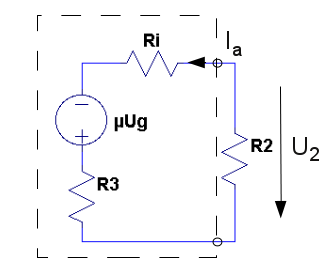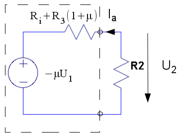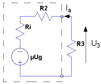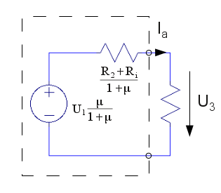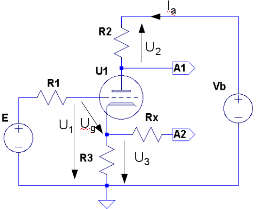
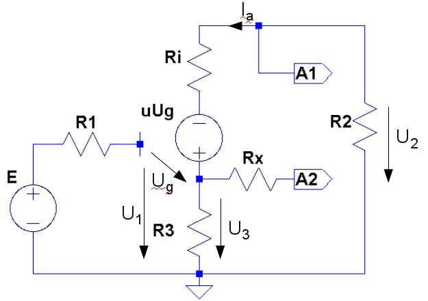
Concertina theoretically

Concertina is one of many phase spliters that is used to create signals with the same amplitude that is 180º out of phase, which is suitable to drive push-pull final stages. Here follows a theoretically investigation of this circuit.


Seek:


samt

Basic equations:


1.1


1.2


1.3


1.4


1.5
Plate:
Use 1.2 and 1.4:


1.6
Use 1.3 and 1.4 with 1.5:


1.7
Use 1.6 and 1.7:


1.8
Calculate 1.8:


1.9
Write the expression for amplification on the plate:


1.10
We rewrites and gets:


1.11
This can be written so you clearly sees that amplification is < 1:


1.12
Cathode:
Use 1.2 and 1.5:


2.6
Use 1.3 and 1.4 with1.5:


2.7
Use 2.6 and 2.7:


2.8
Calculate 2.8:

2.9
Write the expression for amplification on the cathode:


2.10
We rewrites and gets:


2.11
This can be written so you clearly sees that amplification is < 1:


2.12
Finally we set and rewrites 1.11 and 2.11 on a more common way
We can now calculate the amplification on the plate (or cathode) for ECC99:

We now calculate Zut plate and Zut cathode by writing an expression for the 2-poles that is formed by the tube and the cathode resistor R3 with plat as output and by the tube and plate resistor R2 with cathode as output.


Zut for Plate:
Combine 1.2 and 1.4:

3.1
Exchange U3 in 1.3 with Ia*R3 and use in 3.1:


3.2
Expand the expression:


3.3
We now gets an expression for U2 before R2 is connected:


3.4

This looks rather strange but if you calculate output voltage for the circuit with R2 connected one sees that this is the same equation as in 1.11. Use the 2-poles output voltage and calculate the voltage division between Zutanod and R2 which yields us the following equation:


3.5
If we take an example with ECC99 and compare with simulated result we get:


3.6

Zut for Cathode:
Combine 1.2 och 1.5:


4.1
Exchange Ug in 4.1 with U1-U3:


4.2
Expand the expression:


4.3
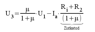
We now gets an expression for U3 before R3 is connected:


4.4
This is a simplier expression than for the plate and we dont need to rewrite it.


If we take an example with ECC99 and compare with simulated result we get:


4.6

Calculation of needed resistor Rx out from cathode to make output impedance equal from plate and cathode.

Plate:
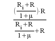
Here output impedance is calculated as the parallell coupling of Zutanod and plate resistor R2 and we get (R denominates either R2 or R3 when we make R2=R3):


5.1
We get:


5.2
Rewrite to:


5.3


Cathode:
Here output impedande is calculated as the parallell coupling of Zutkatod and cathode resistor R3 and we get (
R denominates either R2 or R3 when we make R2=R3):


5.4
We get:


5.5
Rewrite to:


5.6

We now got all we need to calculate Rx that is needed to make these equations equal:


5.7
We start the solving of the equaltion by setting on common denominator:


5.8
Step 2:


5.9
Step 3:


5.10
Final result:


5.11

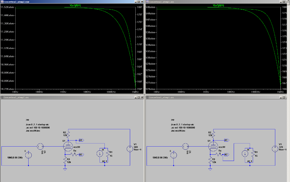
Does this correspond to simulated result? We make an attempt an compare the results:


5.12


Simulated result (simulation modell, dont forget to place the ecc99.inc if you dont have it already)

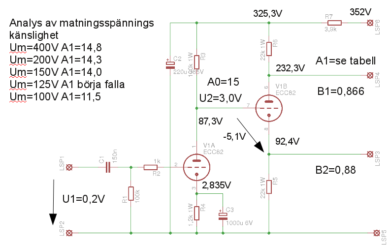
And finally an example with ECC82: