For power amplifiers a normal speaker is usually not directly connected to the output tubes, normal output tubes are high impedance devices that need to be connected to a load impedance in the kohm range to give high power.
Normally an output transformer is used to transform the low impedance of the speaker to a more suitable load-impedance for the output tubes. As an example a suitable load impedance for the popular 300B tube can be ~2.5 kohm so the output transformer should in that case transform the 8 ohms of the load speaker into 2.5 kohm.
To make a good output transformer is not easy and often the output transformer is the limiting factor for the quality of sound in a transformer coupled tube amplifier. The transformer limits the frequency response and introduces distorsion.
OTL (Output TransformerLess) amplifier
There are other ways of designing an output stage so the output transformer can be excluded, amplifiers designed this way is sometimes called OTL's (Output Transformer Less). This technique is quite old and there was OTL's designed already in the twenties, these amplifiers was intended to be connected to speakers with higher impedance in the range of 500 - 1000 ohm's. Although today almost all speakers have impedance of 4 or 8 ohm, earlier it was not so standardised and speakers existed with impedance's of 4, 5, 8, 10, 16, 32, 40, 200, 500 and even 1000 ohms. It is more difficult to make speakers with very high impedance's as they have to use very fine wire in many turns so soon the lower impedance's dominated and now 4, 8 and 16 ohm is the de-facto standardised speaker impedance's.
I started to be interested in OTL's when I found an article in an old HIFI magazine describing an amplifier using the Philips tube EL86. EL86 was designed specially for use with Philips own speakers with 800 ohm impedance. Many TV-sets made by Philips used these tubes and the speakers. The article I found described a more developed version of the Philips design amplifier and data was fantastically good with an output power of 14W, a frequency response flat to 200 kHz and a distorsion at 12W of 0.08%. This article was written in the early sixties and it should be remembered that there was no solid state amplifiers at that time that could show similar performance.
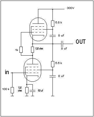
Philips original OTL with EL 86, output power 4.5W with 800 ohm load impedance
The amplifier in the article didn't use the original Philips circuit, as can be seen in the circuit diagram this is a classic single ended push pull stage as is described by Valley and Wallman in "Vacuum tube amplifiers", this circuit has the disadvantage that the tubes has to work in class A thereby limiting the output power. The amplifier in the magazine used a separate tube as a phase splitter making it possible to operate the tubes in class AB permitting higher output power.
I did some experiments in the seventies using various output tubes among them PL519 coupled as triode but my conclusion was that in order to get high output power I needed to use many tubes in parallel and also the heat generated by such an amplifier would be excessive.
Operated as penthode PL519 can pass 1.5A at an anode voltage of only 55V. If it would be possible to build an OTL where the tube was operated as penthode the power dissipation would be much less than if operated as triode.
In the original Philips circuit the two tubes are operated as penthodes and the circuit diagram also give an indication of the problem with this. As can be seen there is a capacitor connected between the screen grid of the upper tube and the output, the reason is that the screen grid voltage has to be constant referenced to the cathode if not excessive distorsion should be introduced. For the PL519 operated as efficiently as possible the anode voltage would be ~90V and the screen grid voltage would be ~200V but it is then not possible to use the same circuit as the original Philips circuit.
Around 1986 I designed an all DC coupled OTL with PL519 operated as penthodes, the principle is shown here
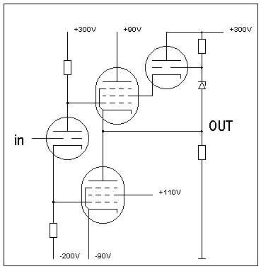
OTL with PL519 operated as penthodes in order to increase efficiency. V1 is 1/2 12AU7, V2 and V3 is PL519 as penthodes and V4 is a PL519 connected as triode.
As can be seen from the circuit diagram V4 supplies screen voltage to V3 which is connected as a cathode follower with the grid connected to the amplifier output, the screen voltage will therefore be constant relative to the to the cathode of V3.
Another problem with using penthode connected tubes in an OTL is that the anode current of the upper tube will be lower than for the lower tube. This is because the anode current of the lower tube must be equal to the cathode current of the upper tube that is the sum of anode and screen grid current. At idle this is not a big problem as the screen grid current will be low but for high anode currents and low anode voltages the screen grid current can be rather high, as an example for an anode current of 1.5A, an anode voltage of 55V and a screen grid voltage of 190V the screen grid current will be ~200 mA or roughly 13% of the anode current. This will introduce an unbalance between the current supplied to the load by the upper and the lower tube and the result will be distorsion.
After some work with the circuit described above I decided that this was not the ideal solution even if it actually would work and give a reasonable result so I gave up and didn't really do any more serious thinking about OTL's until I found out about the 6C33C tube.
The 6C33C is today probably the best tube available for OTL's, it is a pure triode, it can pass high continuous currents and it is relatively cheap and easy to come by, for more info about this tube see:info about 6C33C There have been a lot of OTL amplifiers designed with this tube with many different circuit designs.
OTL circuits
Today mainly two different circuits are used in OTL amplifiers, Futtermans single ended circuit and the circlotron. I have choosen to use a variation of the futterman circuit invented by Technics.
In the simple single ended pushpull configuration with separate phase splitter, the upper tube works as a cathode follower and the lower tube works as a standard cathode grounded amplifiers stage, the tubes will have different output impedance and distorsion will be introduced if the circuit is driven hard.
Single ended push-pull, (SEPP) with separate phase splitter.
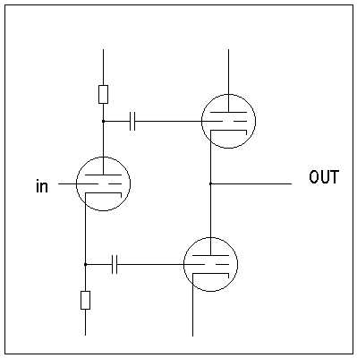
Futterman circuit
This is the Futterman circuit, invented by Julius Futterman in 1954. This circuit provides balanced drive to both tubes by returning the cathode of the phase splitter to the output, this makes the circuit more balanced and both output tubes actually operates as ordinary cathode coupled amplifiers, (even though Futterman thought that they worked as cathode followers). The output impedance of this circuit is Rp/2 so for two 6C33C the output impedance will be ~40 ohm.

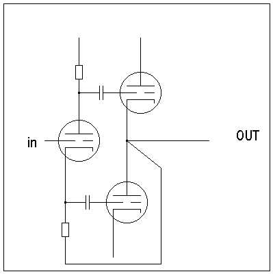
Technics variation of Futterman
This is the Technics circuit which is a variation of the Futterman, here both tubes act as cathode followers and the output impedance is Rp/2*(1+µ) so for two 6C33C this will be ~80/2*(1+2.7) = 10.8 ohm.
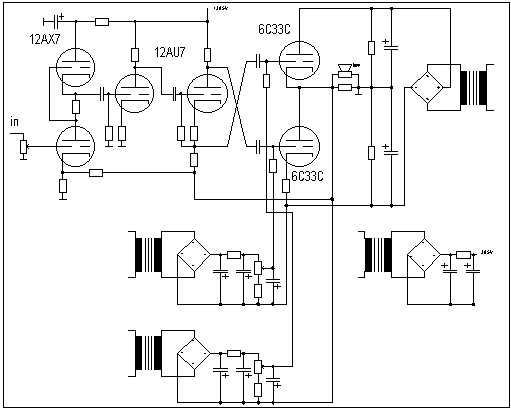
My OTL amplifier
As can be seen from the circuit diagram I have used a SRPP coupled 12AX7 as the first stage. Output power is 2 * 25W at clipping, distorsion is 0.25% at 20W and 0.05% at 2W. Response is flat from 10Hz to 200 kHz, measured output impedance is ~1.5 ohm with 17 dB feedback.
I have now used this amplifier for more than one year and have not experienced any problems what so ever. I check idle current of the output tubes every month but so far the current has not changed at all. The sound is very nice and crisp without being tiring, transients are reproduced exactly and it is easy to hear that this amplifier has real wide bandwidth.
Update 20030331!
After a lot of experiments I have now changed the feedback circuit and increased the amount of feedback, the frequency response is now from ~ 2Hz to 200kHz, -1dB, (the high frequency response is limited by a low pass filter on the input). The rise time is now 1 us and the amp is completely stable with different load, (even with 8 ohm and 6.8 uF there is no ringing, only a minimal amount of overshoot). The output impedance is now measured to 0.3 ohm, (output voltage was measured with 4 and 8 ohm load with same input voltage, from this the output impedance was calculated).
Update 20051115!
I have receieved numerous E-mail lately asking why I have not published the complete schematic of my OTL including component values. The simple answer is that if you send me an E-mail I will in most cases send you the complete schematic, especially if you give me some information about yourself, your interest in tube amplifiers and OTL's in particular.
Update 20060101!
My new high power OTL amplifier
I am now starting to see the end result of my latest design effort, an OTL with higher output power, the circuit is presented below
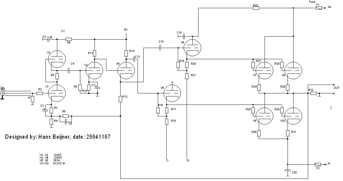
My goal is to get 100W output power in 8 ohm with good reliability, as of today, (20060101) I get 80W at clipping, (clipping defined as the point of 1% distortion). Distortion at 1W is ~0.03% and at 1dB below clipping ~0.3%. In order to reach 100W I intend to raise the anode power supply to the output tubes from 150V to 160V, current for each output tube is ~200mA.
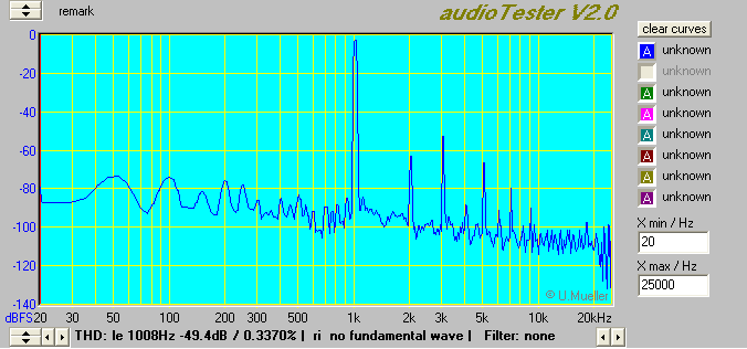
Spectrum of output signal at 1dB below clipping
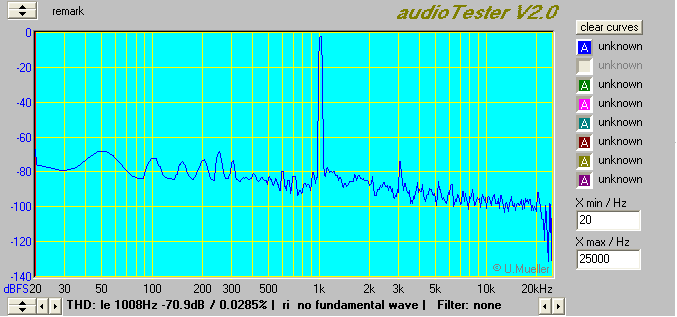
Spectrum of output signal at 1W output power
OTL related links
Andrea's page
Includes a lot of information about OTL's. He is using a similar circuit to mine except that he doesn't use a SRPP stage.
Another page with OTL's
Here they advocate the use of the circlotron circuit, good theoretical analysis of different circuit topologies.
Back to Tube amplifiers