The purpose of this paper is to explain the selection process and trade-offs involved in choosing
the circlotron as the optimal topology for a high-power OTL amplifier. The issues involved in
making this selection include circuit simplicity, balanced performance under small- and
large-signal operation, and achieving low output impedance (and hence a high damping factor)
without the excessive use of feedback.
For many of us, the vacuum tube remains the only
acceptable electronic component for amplifying music. Endless debates
and discussions on the merits of solid state versus tubes rage on, but
we find that the transparency and realism offered by a device
consisting of metal and vacuum just cannot be matched by silicon for
sheer musical enjoyment and getting as close as possible to the
original sound. Prove what you like, tell us we're imagining things,
but we know it just sounds better.
However, by insisting on all-tube amplification, there is classically a
major penalty to be paid in the power amplifier. Tubes are simply not
designed to couple directly to today's modern low impedance speakers,
and a transformer must be used to match the power output to the load.
Even with finest modern materials, the output transformer
remains the weakest link. At low frequencies its finite inductance
steals current away from the load, and at high frequencies its stray
capacitance, leakage inductance, and high-frequency copper losses
combine to attenuate amplitude and introduce severe phase shifts. From
the early days of hi-fi, audio designers strove to create the ideal
amplifier. Much effort went into optimizing power transformer design,
and even now, the seminal text books on transformers and basic magnetic
analysis date back to this early time.
H.S Black discovered negative feedback for electronics in
1934, and it was immediately realized that feedback could go a long way
to curing many of the problems introduced by the output transformer and
other the electronic amplifying devices. In fact, it was felt that the
quality of an amplifier was limited only by the amount of negative
feedback that could be applied.
How much feedback that can be realistically appied is
limited by how much phase shift
exists from input to output of a system. Most of the feedback-limiting
phase shift in a vacuum tube amplifier occurs in the output
transformer; therefore, if only it could be eliminated, large amounts
of negative feedback could be employed, thus creating the perfect
amplifier.
Today we realize that negative feedback is not the panacea it was once
thought to be. In small to moderate doses it can be beneficial, but, as
solid-state amplifier designers eventually discovered a generation
later, too much feedback always sounds less musical than too little
feedback.
As with any problem in engineering, the optimal solution
is not to fix it with additional circuitry, but to remove it
altogether. It seems logical then, that if an amplifier can be no
better than its output transformer, eliminating the transformer
altogether should result in superior performance. Hence the quest for
the holy grail of tube amplifier design that has fascinated and
tantalized audiophiles for over 40 years: how to design a rugged and
powerful Output TransformerLess (OTL) amplifier.
The biggest obstacle to building an OTL is the problem of impedance:
tubes are designed to be high-voltage, low current devices, and modern speakers
need high currents at relatively low voltages. The plate resistance of a tube,
typically high, limits the amount of power the tube can supply for a given rail voltage.
Plate impedance alone does not completely determine the available power.
It is also affected by whether your choice of circuit forces you into
Class A operation (all power tubes always conduct), or whether Class AB (half the tubes may cut off
during a half cycle) or Class AB2
(same as AB, but grid is driven positive, resulting in grid current flow) are also possible. However, once
the class of operation is determined, available power is determined by plate resistance.
Even using several of the best tubes available, plate
resistances are still considerably higher than load resistances. That's
OK, you can build an OTL amplifier; it will just be relatively
inefficient. For example, a single 20 Ohm plate resistance tube
supplying a 4 ohm load can never be better than 16% efficient
(=4/(20+4) x 100%). Reasonable power can still be provided to the 4 ohm
load, but it requires a higher supply voltage than the peak output
voltage, and you have to accept this and design for the dissipation of
the circuit.
While we cannot change the inherent plate characteristics of a tube, we
can change the way the tube is arranged and driven in an amplifier circuit.
This can have a dramatic effect upon the output impedance of the
amplifier which tells us how stiff a voltage source we have made. This is also expressed
by some as the damping factor of an amplifier - the lower the output impedance, the
better voltage source you have achieved. The amplifier will then be better able to handle the
nonlinearities, distortions, and back emf
produced by the usually very complex speaker load.
The common available topologies for OTL amplifiers have some very important
differences in the output impedance characteristics which must be carefully
considered when selecting which topology you want to use. Although the power
capabilities of the different topologies may remain unchanged when they operate in the
same class (A, AB or AB2), the sonics may be substantially different due to the wide
range of output impedance that can be achieved.
It is important to point out that discussions of plate impedance must be done on
small-signal level. In reality, the characteristics of a tube are nonlinear, and the plate
impedance, derived at a single operating point from the slope of the I-V characteristics of the
tube, will change drastically over a wide range. However, the results of
small-signal analysis are still valid - if we come up with a topology
that minimizes small-signal output impedance, it will invariably work much
better in the large-signal domain also. In other words, it will probably sound better
under real conditions.
For the sake of this paper, the 6C33C-B tube will be used for numerical example.
At a bias voltage of 145 V,
and a plate current of 400 mA, this tube has a plate resistance of 100 ohm, and a gain of 2.7.
At lower currents, the plate resistance increases, a factor to bear in mind when selecting the bias point
of the tube. At higher currents, the plate resistance drops - fortunately so, otherwise even the 6C33C-B
would be horribly inefficient in supplying a 4 ohm load, and a high-power OTL amplifier would not be
practical. At a plate voltage of 70 V, and 1 A current, the resistance of this tube drops to 40 ohm.
This changing plate impedance is another reason to strive to get the output impedance
level as low as possible. If the
output impedance is high relative to the load, and it changes substantially with current,
a significant amount of
odd harmonic distortion is created.
The first commercial OTL available was the Stephens OTL
which could only power its own specially-designed 500 ohm loudspeaker.
It was not a successful product. But this early example demonstrates
the primary difficulty of OTL design: how to couple a low- impedance
load to a high-impedance vacuum tube without using an
impedance-matching transformer. With the introduction of the 6AS7G
twin-power triode in 1946, this task started to appear feasible.
Its plate resistance is listed at 280 ohms per section; if enough tubes
could be combined in parallel, it wouldn't be too difficult to drive a
typical loudspeaker load, which at that time was around 16 ohms.
To get the lowest possible output impedance for a given tube,
we must use a cathode follower configuration. This gives an output
impedance of Rp/(1+u) where Rp is the intrisic plate resistance, and u is the gain of the tube.
Single-tube cathode follower OTLs can and have been built,
although they are very limited in output power, and the problem of dc current in the
load must be dealt with.
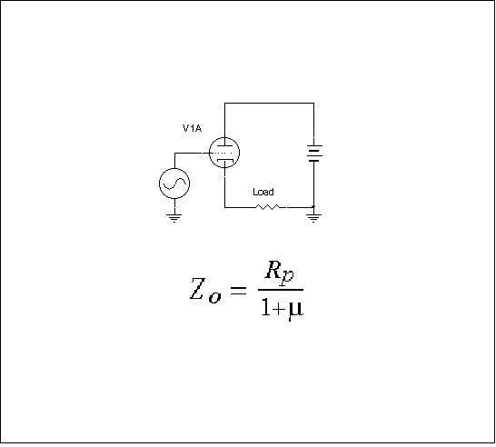
Fig. 1: Cathode Follower OTL
In order to prevent dc current from flowing through the speaker load of this
configuration, the speaker can be paralleled with a large inductor which will
shunt the dc bias current. This is still an OTL - there is no transformer between
the power tube and the load, and none of the detrimental effects of the transfer
function from input to output of a transformer coupled load. The most
important benefits of OTLs are eliminating the transformer wire, and connecting
the speaker directly to the power tube with no other elements in series. However, the
low-frequency loading effect of the inductor will detract from the bass performance of this configuration.
This amplifier must, of course, operate in Class A regime only.
Since we are concerned here with much higher output
power designs, this topology will not be considered further.
An OTL amplifier can also be connected with the output
tube having its cathode grounded. In this common-cathode configuration,
the output impedance of the amplifier is much higher, given by Rp, the
plate resistance alone. The gain characteristics of this configuration
are, of course, different from the cathode follower, and it is
preferred by many single-ended purists.
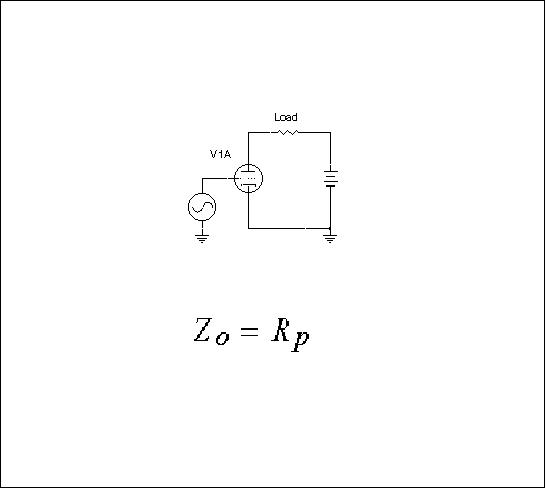
Fig. 2: Common Cathode OTL
As with the cathode follower OTL, the problem of dc current in the load can be mitigated by an inductor
in parallel with the load. Also, it must be operated Class A, so it is of little real interest in designing a
high power OTL
In 1951 Fletcher and Cooke demonstrated a balanced push-pull
cathode follower output stage using eight 6AS7G's that generated
6.32W into 16 ohms. This approach had two distinct disadvantages:
its operation was limited to class A, hence the low-power, and its'
output impedance was rather high at 2Rp/(1+u).
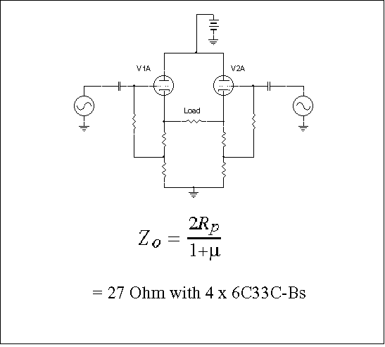
Fig. 3: Push-Pull Cathode Follower OTL
Using two tubes in parallel in the cathode follower configuration of the
previous section would give Rp(2+2u), the lowest achievable open loop output
impedance using a pair of tubes. The push-pull cathode follower output impedance
is four times the theoretical minimum because the two cathode followers are in series, not in parallel.
If four 6C33C-B tubes were used in this particular configuration, biased at
145 V and 400 mA each, the open-loop (i.e. before any feedback is considered)
output impedance would be 27 Ohms.
Also in 1951, Peterson and Sinclair proposed what was to become the standard
OTL output topology, the Single-Ended Push-Pull, or SEPP. The output circuit is
simple, well-suited for class AB or AB2 operation, allowing more output power,
but is has one outstanding disadvantage: it is inherently unbalanced.
Fig. 4: Single-Ended Push-Pull OTL
In the SEPP output stage the load appears in the cathode circuit of the upper
tube and in the plate circuit of the lower tube. If a conventional push-pull ground-referenced
driver stage is employed, the upper tubes behave as cathode-followers while the lower
tubes act as common-cathode amplifiers.
This creates an imbalance of gain and output impedance between the upper and lower stages,
unacceptable in good amplifier design.
If true push-pull operation is to be achieved, the upper and lower tubes must be
driven with equal but out-of-phase signals, but the presence of the load in the input
circuit of the upper tubes makes this difficult to achieve in practice.
In a conventional push-pull amplifier using solid state devices, this problem of balance is overcome
by using a P-channel device. Since we only have single-sex electron tubes,
and positron tubes do not exist (except theoretically, and perhaps amongst
audiophiles of the future on the Starship Enterprise), the SEPP cannot be driven
directly, and it must always be considered in conjunction with a suitable drive scheme.
In 1954, a self-taught New Yorker by the name of Julius Futterman published the
most famous solution to the problem of a balanced drive for the SEPP. He proposed
that the cathode resistor of a split-load phase inverter be returned to ground through the
load, rather than to ground, as was the normal practice.
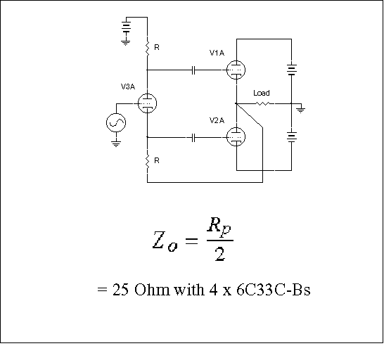
Fig. 5: Futterman OTL
This arrangement results in equal but opposite drive signals being applied
between the grid and plate of both sets of tubes. He went on to claim that when
so driven, the output tubes are operating as cathode followers. Unfortunately, this is
not correct, and Futterman's driver design did not achieve cathode follower operation.
This is because the 100% positive feedback introduced by standing the phase
splitter on the output voltage effectively canceled the 100% negative feedback from the
load that produces the cathode follower effect in the first place.
In other words, Futterman succeeded in converting the upper tube into a
common-cathode amplifier, thus matching the behavior of the lower tube,
and in so doing lost the cathode-follower impedance advantage! Instead of
getting the desired theoretical output impedance of two parallel cathode followers,
Rp/(2+2u), the Futterman OTL has the output impedance of two parallel common
cathode amplifier tubes, Rp/2.
Futterman's solution to provide balanced drives to the SEPP is best known in the
US. In Japan, OTL designers mostly used a cathode-coupled phase inverter driver
first proposed by Hiroshi Ameniya in 1955. While this driver provided lower drive
impedance and twice the signal swing of the split-load phase inverter, it too resulted
in the output tubes behaving as common-cathode amplifiers with their attendant high
source impedance of Rp/2.
It is important to note that the Futterman and other schemes proposed for the
SEPP drive use feedback to achieve the balanced signals. But even with a
high gain tube driving the output stage, the output impedance is relatively high,
so the feedback only serves to balance the drives. In this regard, the gain of the driver tube is not
fully utilized to achieve full benefits.
If four 6C33C-B tubes were used in the Futterman OTL, biased at 145 V and
400 mA each, the open-loop output
impedance would be 25 Ohms (coincidentally, about the same as the Push-Pull Cathode Follower).
The Futterman circuit, and other solutions to driving the SEPP, allow for Class AB operation. Care must
be taken if pushing into Class AB2 since the driver circuits are not balanced perfectly, and grid
current will introduce assymetry between the top and bottom tubes, and resulting distortion.
The Futterman is a very clever solution to the problem, but it has the
disadvantage of making both tubes behave like common-cathode amplifiers,
with their inherent high output impedance. There is a variation of this circuit
which appears solves this problem. If the drives to the two tubes are interchanged,
the circuit now behaves as a true pair of voltage followers, and the output impedance
is dropped down to the theoretical minimum of Rp/(2+2u).
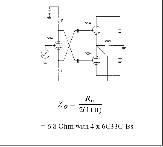
Fig. 6: Variation of Futterman OTL
If four 6C33C-B tubes were used in this circuit topology, the open-loop
output impedance would be about 6.8 Ohms, 4 times lower than the original Futterman!
Of course, the lower output impedance does NOT mean that the variation on the Futterman can provide
four times as much power. The power handling capabilities of both circuits remain the same, since it is
the tube plate characteristics that determine power, as discussed earlier. The circuits will need different
drive requirements to get there, but they can both run at the same power level.
Also, this low output impedance could only be achieved
with a high gain tube. If pure triode operation were desired for the
amplifier,
and a realistic gain tube were used, the output impedance would be
closer to 3 times lower than the original Futterman circuit.
Instead of concentrating on how best to unbalance the drive signals
to compensate for the inherent unbalance in the output stage, a simple
modification can be made to the output stage that eliminates the unbalance
altogether. If the load and the two power supplies are allowed to float with respect
to ground, and if the position of the lower supply and output tube are interchanged,
the inherent unbalance of the SEPP is completely eliminated! This arrangement was
first used in the Electro-Voice Circlotron of 1955, but was never applied in a commercial
OTL until Atma-Sphere Music Systems came out with their MA-1 in the late 1980's.
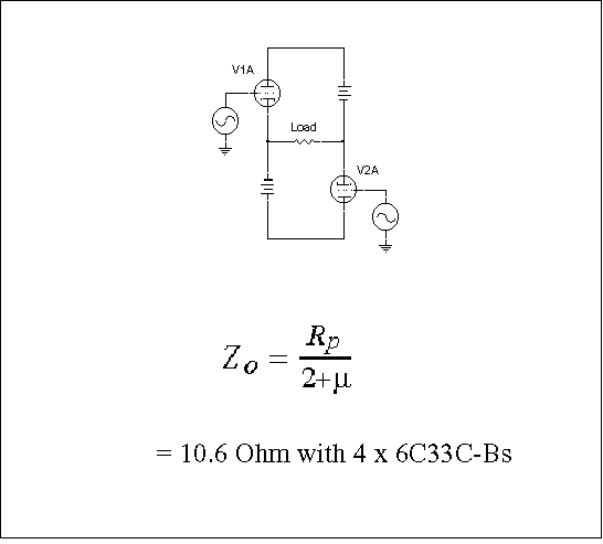
Fig. 7: Circlotron OTL
With the Circlotron arrangement each output tube now behaves
in an identical manner. Half the signal across the load appears in the
cathode circuit of each tube resulting in partial cathode-follower operation. While the
output impedance of this circuit is somewhat higher than the best optimal cathode follower achieved with
the Futterman Variation,
Rp/(2+u) versus Rp/(2+2u), it is
still considerably better than the Rp/2 with identical tubes in a conventional Futterman.
Best of all, a conventional push-pull driver stage will give achieve perfect balance with
the circlotron, without resorting to circuit tricks, and no feedback around a high-gain
tube is used in the
driver stage.
If four 6C33C-B tubes were used in the circlotron topology, the open-loop output
impedance would be about 10.6 Ohms. Again, not quite as good as what can be achieved with the
Variation on the Futterman, but usable.
There are several other advantages to the Circlotron.
Both sets of cathodes are at ground
potential and can therefore be biased from a common negative voltage. With the SEPP,
two bias voltages are required, one ground referenced and the other referenced to the
negative rail.
Also, because of the asymmetrical arrangement of the output tubes with
respect to the rail voltages, any ripple, power line or signal-induced transient voltages
are fed directly into the grid circuit of the lower tubes, via the cathode, where it gets
amplified along with the input signal. The upper tubes are immune from this as the
rail voltage looks into the plates and therefore does not modulate the grid-to-cathode voltage.
The result is a significant hum component at idle and signal-dependent DC offset at
higher signal levels. The only way to prevent this from happening is to provide for
electronic regulation of both power supply rails, although hum can be reduced
significantly with high negative feedback.
With the Circlotron arrangement, ripple and noise on the rail supplies do not
affect grid bias. Any modulation of the rails affects only the tubes' plate voltage.
Ripple and power line induced transients are automatically canceled in the load,
since the load only responds to differential inputs, and these disturbances are common-mode. This is
not true for the Futterman circuits.
Given the benefits of the Circlotron: low source impedance, balanced operation and
high common-mode rejection, it is possible to dispense with negative feedback altogether.
The Atma-Sphere MA-1 is one product that does this. However,
despite using 12 6AS7G's in a Circlotron output configuration,
however, the damping factor is still too low for good compatibility with
many of the lower impedance speakers available. Realizing this,
Atma-Sphere offers a tapped auto-transformer to match the 11 ohm output
impedance of the MA-1 to a one, two, three or four ohm load.
For many tube users, the concept of adding a transformer to the
OTL topology defeats the whole purpose of the exercise - Sorry folks, if it
needs a transformer to work properly, it ain't an OTL! It may still sound very
good, and the auto-transformer design may be an improvement over other approaches,
but it's not the holy grail. (Note: it may also be a lot more reliable than a pure OTL -
an important consideration for anyone making these amplifiers for a living.)
Perhaps a better way to achieve a low output impedance is to add some
overall voltage feedback. Because of the two balanced outputs of the Circlotron,
two feedback paths must be used, as in any balanced design. Since the
open-loop output impedance is already low in the circlotron arrangement,
not much feedback is needed to get the job done. When operating into a
4 ohm load, only 10 dB of feedback is needed to give an output impedance of less than 1 ohm.
Adding some feedback to the circlotron has the added advantage of correcting for the
distortion created in the output stage under large signal excursions. It also
permits low-distortion Class AB2 operation of the output tubes. If the driver
impedance is kept low and can source sufficient current, it is possible to get
almost twice the power that can be achieved with class AB1 operation. But
even with low driver impedance, high open-loop distortion is the result when
positive grid current begins to flow. If left uncorrected it appears as if the output
waveform is clipping. By applying corrective feedback the driving voltage is
automatically increased to compensate for this effect, and the full potential of the
output tubes can be realized.
The best output tubes for OTL's were all originally developed for
service as series pass devices in voltage regulators. These include
the 6AS7G, 6080, 6082, 6336/A/B, 7236 and 7241. All these tubes are triodes.
This may come as a surprise to some who are only familiar with Futterman-based
designs, since these almost exclusively
rely on pentodes in the output stage. While Julius Futterman's original OTL design
used eight 12B4 miniature triodes, he soon switched to pentodes. This is because
with a typical high-impedance ac-coupled driver, incapable of driving the output tube
grids positive, the triode cannot generate as much output power as a pentode.
But pentodes are inferior in most other respects to triodes.
(Anyone interested in an excellent discussion of why triodes are superior to
pentodes for OTL service is urged to read Clive P. Locke's "60W OTL/OCL
Triode Power Amplifier" in Glass Audio Vol.4 No.4 1992.)
Until recently the best power triode for OTL's was the 6336A. Very popular in
Japan and France, it was even mentioned favorably by Futterman in his
famous 1954 paper in the JAES. Bothered by the high grid emission of the
6AS7G, as well as by its low mu of 2, he remarks that the then new Chatham
6336, with its higher mu of 2.7, and its 100 ohm plate resistance
(with both sections in parallel) performed well in his design.
The 6336A was exceeded only by the Sylvania 7241 triple-triode in low
plate resistance. Rated as having a plate resistance of 67 ohms at 550mA,
the 7241 never caught on overseas because it was expensive and hard to find.
Another tube with limited availability was the EC33C. Made in the Soviet Union
especially for the Japanese market (according to Jean Hiraga in "Les amplificateurs O.T.L.")
it was presumably a forerunner of the by now famous Sovtek 6C33C-B.
Previously only available for Soviet military use, the 6C33C-B power triode
is now readily obtainable in the West, ever since the fall of the Iron Curtain.
Very similar in performance to the 6336A but far cheaper, this tube is built like a
tank with its thick glass and internal bracing to reduce microphonics.
It has quickly become the tube of choice for OTL designers around the world.
The final topology selected was the circlotron, due to its relatively low output impedance, perfectly
balanced operation, circuit simplicity, and low distortion with large-signal and Class AB2 operation.
In designing this Covi Mark II circuit, the following modifications
were made to the standard circlotron OTL:
As used in the Covi Mark II Circlotron OTL, four 6C33C-B
tubes generate over 100W into 4 ohms and over 125W into 8 ohms running
class AB2 with a plate voltage of 145V. At the sine wave peaks, that's
a real 200 W instantaneous, into 4 ohms, which means each 6C33C-B is
delivering 3.75 A! Output power can be increased even further (with a
corresponding reduction in reliability) with higher plate voltages. For
some comments on how reliable this circuit and these tubes are, go to
6C33C-B OTL amplifier reliability.
Further details of this output stage of this amplifier are given on the
OTL Amplifier Output Stage Schematic
web page.
The input stage is described in detail on the
OTL Amplifier Input Phase Splitter Schematic web page.
Page counter started December 31, 1996. You are visitor

Home URL: http://members.aol.com/aria3/index.html
© Copyright 1996 Tube Lovers Anonymous. All rights
reserved. Links to this page encouraged.
Comments and suggestions to this page welcome.
Email to aria3@aol.com
Original: 12-11-96, revised 1-22-97
