Beauty of the Beast: understanding, improving, modding the Eico 666 Tube tester.
Copyright © Jan 2005. Author: Dmitry Nizhegorodov (dmitrynizh@hotmail.com). My other projects and articles
|
2. Introduction 3. AC UI as plot 4. 1/4 Inch Taps Mod 5. Socket-plug Mod ideas 6. Built-in Tracer Circuitry Mod 7. References
|
|
1. Brief
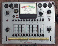
Eico 666 is a capable tube tester, yet its use scenarios can be multiplied with only modest efforts invested in understanding its schematic, regimes, and ways to add new regimes.
2. Introduction
Eico 666 is capable tester, known to be able to supply voltages and currents adequate for most tubes. It performs emission/conducance tests as well as leakage tests. The short summary, see [1] says:
 DYNAMIC CONDUCTANCE TUBE TEST: Composite indication of mutual
conductance (Gm), plate resistance (Gp) and peak emission capability.
DYNAMIC CONDUCTANCE TUBE TEST: Composite indication of mutual
conductance (Gm), plate resistance (Gp) and peak emission capability.
The manual [2] explains the regimes and elaborates on various procedures. Dynamic conductance is the "merit" test for which the simplified schemaic shown on the left is supplied. It is not clear how the volatges Fi1-Fi3 form, although it is apparent, after careful reading, that "Fi" stands for AC volatge. Is grid voltage in-phase with the plate voltage? Not clear, yet the fact that tester seem to measure tube parameters in AC domain, where the AC is taken directly from wall transformer, is interesting enough.
Ideed, after careful reading of the full schemaic (available from [bama]), I was able to come up with this diagram, showing tube under test in Merit mode.
Note that the grid indeed receives positive (in-sync) AC signal. It would be pretty trivial to flip the polarity and let it test tubes such as 6bq5 with negative (out-of-phase) grid AC.
This thought triggered my interest; I became curiuus about how to a DC mode to my eico666 without changing its schemaic too radically, and how to better utilize its AC regimes. The former seems obvious and hence desirable, the latter appeared odd but led to very interesting possibilities.
3. AC UI as plot
When triode plate sees a fixed voltage (aka "DC voltage", term which is standard but a misnomer by itself) its plate current can respond to changes in grid voltage and the slope of the change is called transconductance. You may think that nothing like that can be seen in AC-plate AC-grid regime; but what about AC-plate, fixed-grid regime? Plate voltage swings across negative, unusable range, when the tube is closed, then across useable, positive range - through each value from zero to 1.414 volts of VAC. If we could plot corresponding current swing we would see ... a plate line!
4. 1/4 Inch Taps Mod
 Shown on the right are the mods to EICO666 permitting to obtain Up, Ik
and supply external Ug. The new wires are in read ink. These are the
only changes required. A scope in XY can be connected to the Up, Ik
taps and the plate line will be displayed on the screen.
Shown on the right are the mods to EICO666 permitting to obtain Up, Ik
and supply external Ug. The new wires are in read ink. These are the
only changes required. A scope in XY can be connected to the Up, Ik
taps and the plate line will be displayed on the screen.
 Shown on the right are further mods to Eico-666 permitting us to obtain
Up, Ik and supply external Ug, as well as supply additional insertions
into plate B+ and screen B+. The Up and Ik taps are combined into
single stereo jack, J1. This jack can be 1/8" in size (mini phone
jack), as used on PC audiocards. The grid jack is stereo 1/4", with two
normally-closed contacts on each channel, connected together. This way,
when nothing is inserted, the jack represents a shorting connector. In
a similar way, screen B+ jack J3 and plate B+ jack J4 are stereo 1/4"
jacks with shorting bypass. Note: it is better to locate NOS 1/4" jacks
with reliable contacts, as many modern 1/4" audio jacks are of poor
quality.
Shown on the right are further mods to Eico-666 permitting us to obtain
Up, Ik and supply external Ug, as well as supply additional insertions
into plate B+ and screen B+. The Up and Ik taps are combined into
single stereo jack, J1. This jack can be 1/8" in size (mini phone
jack), as used on PC audiocards. The grid jack is stereo 1/4", with two
normally-closed contacts on each channel, connected together. This way,
when nothing is inserted, the jack represents a shorting connector. In
a similar way, screen B+ jack J3 and plate B+ jack J4 are stereo 1/4"
jacks with shorting bypass. Note: it is better to locate NOS 1/4" jacks
with reliable contacts, as many modern 1/4" audio jacks are of poor
quality.
 Shown on the right are plugs to go into jacks J1, J2, J3, J4. Of
particular interest are the plugs for J4 and J3. Shown are 3 variants -
the first one providing additional AC voltage swing by means of an
extra transformer; the second one providing extra AC voltage and a load
resistor, the third one providing voltage, load and half-wave
rectification, sparing the tube from unwanted negative semi-waves.
Shown on the right are plugs to go into jacks J1, J2, J3, J4. Of
particular interest are the plugs for J4 and J3. Shown are 3 variants -
the first one providing additional AC voltage swing by means of an
extra transformer; the second one providing extra AC voltage and a load
resistor, the third one providing voltage, load and half-wave
rectification, sparing the tube from unwanted negative semi-waves.
Jacks 2, 3, 4 can be connected to a box hosting an extra AC voltage source implemented as a variac with a step-up transformer of medium power (50-100W), a regulated, stabilized, floating voltage supply that can serve as negative or positive bias and a small 3-digit digital voltmetter mounted inside for convenience. Jack j1 can go directly into computer via a cable with protective diodes inserted.
5. Socket-plug Mod ideas
Described above are the mods permitting many new regimes for Eico-666. Two sockets were added to monitor tube plate voltage and cathode current, a socket was added to provide external grid voltage, 2 sockets were added to "inject" additional circuitry alone plate and screen B+.yet tehre is another way to communicate to EICO-666, namely letting it to house a tube in a socket, letting it to supply th etube with appropriate heating/filament voltage, yet diverting everything else to outside circuitry. This is possible because in tube testers like Eico-666 (1) the control levels are associated with pins; all tube sockets have pins N connected to level N, and level N has M positions; More specifically, in Eico-666 M is 6: ground, filament, screen, plate, grid, disconnected.
Now consider that all tube pins except the heating/filament pins are disconnected. Then consider a plug inserted into a spare socket, attached to an external device. This device then can control the tube by supplying voltages. loads and monitoring currents on each pin. No re-wiring of the tester is required.
The arrangement outlined in the previous paragraphs has a shortcoming of requiring complex switching to send Ug, Up, Us and the ground to appropriate pins. The following is more satisfactory arrangement: an external device is implemented providing Ug, Us, Up and cathode as jacks. A small extension patch board occupying the section above the 8pin and 9 pin socket area of Eico-666 is implemented, housing two tube plugs, two tube sockets, one tube bulb cap and 10 jacks. The jacks onto the external device then can be connected with patch cables to appropriate jacks onto the extension board.
6. Built-in Tracer Circuitry Mod
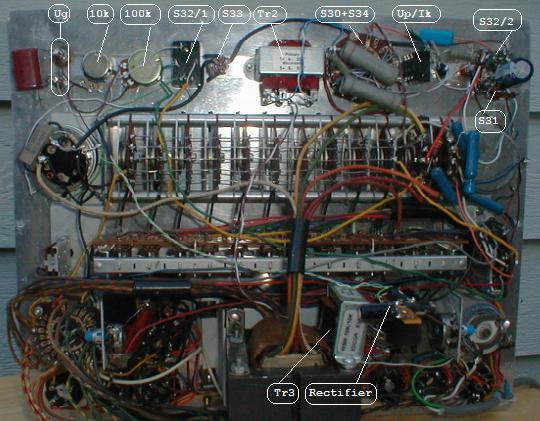
The following is the schematic of Eico-666 with the controls and circuitry wired inside of the chassis.
the load resistors connected to the switch S30 are (top to bottom): 100k, 33k, 10k, 5k, 3k.
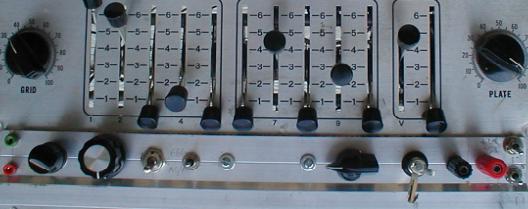
The new controls are mounted on a strip of aluminum covering the roll chart area; the roll chart itself was carefully unscrewed, removed and stored in a safe place.
7. References
[bama] http://bama.sbc.edu/eico.htm[tone-lizard] http://www.tone-lizard.com/Eico.html, http://www.tone-lizard.com/Eico666.html
Author: Dmitry Nizhegorodov (dmitrynizh@hotmail.com). My other projects and articles